
All parts in a classical movement
In the figure above you can see the 8 basic function blocks that constitute the movement and how they are related to each other. We can see the mainspring system followed by the accelerating wheel train to the oscillator or balance system. Between the wheel train and the balance system we find the escapement which is the function that both regulates, in a precise way, the unwinding of the main spring and gives the balance its necessary impulse, for each turn, to keep it swinging.
The mainspring is wound via a very clever system called the keyless works. It transmits the turn of the winding button to the mainspring. When the winding crown is pulled to its set position the keyless works connects with the motion works and the hands at the dial can be turned. In normal operation the hands are driven from the wheel train via the cannon pinion which is friction-fitted to the arbor from the wheel train. This friction fit allows the hands to turn when the movement is in the set mode.
Click on the boxes!
All pictures are taken using inexpensive flea-market and sceleton watches. As an amateur don’t start with your new watch!
Mainspring System


The Barrel (182) contains the Mainspring which constitute the power source of the watch, top and bottom sides as shown in the photos below. The outer end of the Mainspring is fitted to the Barrel by some type of clever hook that engages a slot in the barrel circumference. The inner end of the main spring has a slot that fits to a hook at the Barrel Arbor (195). The bottom of the barrel is fixed to a wheel with teeth, or the barrel rim itself has teeth as in the pictures. These teeth are connected to the wheel train.
The picture to the left is from a sceleton movement where the Mainspring in the Barrel (182) can be seen in its fully wound state.
To the right in the picture below the squared fit of the Barrel Arbor (195) to the Ratchet Wheel (415) can be seen.

The wheel train
The wheel train changes the speed of the barrel, one revolution in 7 hours,
to the escape wheel’s one revolution in 5 seconds!


The Mainspring Barrel circumference (first wheel to the left) has teeth that are connected to the next pinion in the wheel train. The rotation of the barrel is accelerated in 4 steps, including the escape wheel pinion. As can be seen in the figure the first wheel after the barrel is the center wheel, also called the 2nd wheel. The name is given because that this wheel, in almost all cases, is in the very center of the movement aligned to the arbor of the watch hands. As a matter of fact this wheel has a rotational speed of one revolution in an hour, and hence the minute hand is attached to its arbor.
The speed is further increased via the third wheel to the fourth wheel, which makes one revolution per minute and has the second hand attached to its arbor. Finally the fourth wheel engages the escape wheel pinion.
Center Wheel (201)
Third Wheel (210)
Fourth Wheel (224)
Escape Wheel (705)
Escapement
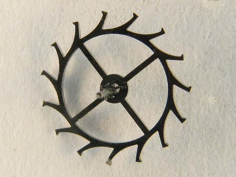


The escapement, escape wheel and pallet lever, together with the balance system is the real heart of the movement. The escape wheel and the pallet lever together perform two different but equally important tasks: to control the rate by which the main spring unwinds (oscillator with a stable frequency) and to repeatedly give the balance wheel its needed impulse.
The picture shows the Escape Wheel (705) which is the last wheel in the wheel train that is powered by the Mainspring.
The two tasks are implemented by the geometry of the pallet jewels and Escape Wheel teeth. If not locked by the Pallet Lever, the Escape Wheel would accelerate to a very high speed and the Mainspring would unwind in just a few seconds.
The Escape Wheel (705) pinion is driven by the Fourth Wheel (224). The Escape Wheel in turn interacts with the Pallet Lever (710).
The Wheel Train starts to the left with the Barrel (182) which drives the Center Wheel (201) pinion. The rotation speed is further increased via the Third Wheel (210) to the Fourth Wheel (224), which makes one revolution per minute and has the second hand attached to its arbor. Finally the Fourth Wheel engages the Escape Wheel (230) pinion.
In this figure the Escape Wheel, the Pallet Lever, and Balance are in their respective right places.
The Balance


The escapement, Escape Wheel and Pallet Lever, together with the Balance System is the real heart of the movement. The Escape Wheel and the Pallet Lever together perform two different but equally important tasks: to control the rate by which the Mainspring unwinds and to repeatedly give the Balance Wheel its needed impulse. The Balance Wheel and the Hairspring constitutes a mechanical oscillator with a stable frequency.
The figure shows the top side of main plate without any components. At the top right are the Balance Bridge and the Balance. At the bottom right are the Pallet Lever Cock and the Pallet Lever.
This figure shows the Pallet Lever put into its position and fixed by the Pallet Lever Cock. The Balance is also at its correct position on the main plate.
Here the Balance Bridge is in place. The end stone of the balance shock-protection system in not mounted.
This figure shows the end stone and the balance shock-protection mechanism. One great improvement in watch design was when the shock-protection system was introduced. The idea is to prohibit breakage of the balance arbor pivots by allowing the jewel bearing and an end-stone - also called cap-jewel - to move controlled by a spring. The spring holding the shock-protection together is of different shapes in different watch manufacturer's designs.
Here the Escape Wheel is in place completing the heart of the movement.
The regulator, a part of the balance system, is the fine tuning system to make the balance oscillate at the correct frequency. It's like finding the right pitch on a violin string by gliding a finger up and down the string. The violin player does this to regulate the length of the string and hence get right frequency. In the watch movement you control the effective length of the hairspring in a similar way by moving the regulator index arm, bottom left in the figure. N.B that the movement is in operation in the figure, the Escape Wheel has moved some steps during the exposure of the photo.
Motion Works including the Cannon Pinion


The motion works has two roles: the first is to gear down the speed to the hour hand and the second is to allow for setting of the hands to the correct time. The hour hand is attached to the Hour Wheel (250) arbor. The Center Wheel (201) arbor, to which the minute hand is attached, is fitted through a hollow pinion tube.
This tube is called the Cannon Pinion (240). It is friction fitted to the Center Wheel arbor and its pinion drives a wheel called the Minute Wheel, which in turn decelerates the turning rate of the center wheel to the hour wheel by a factor of 1:12, giving the Hour Wheel the turning rate of one revolution in 12 hours
The Cannion Pinion (240)
The Hour Wheel is centered by the Cannon Pinion but is not fixed to it. In this way the Cannon Pinion and the Hour Wheel can rotate around the same center axis but at different speeds.
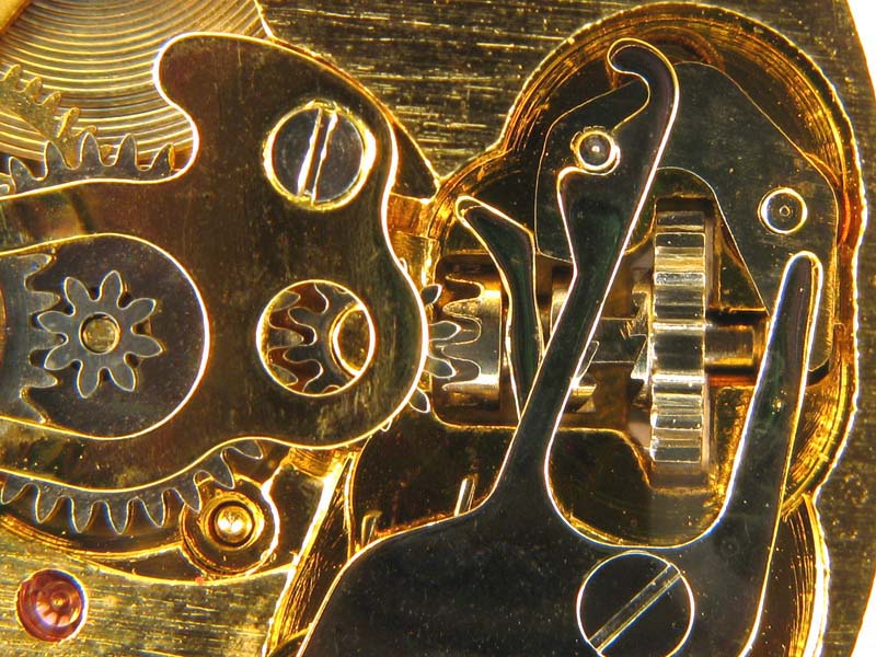
Turning the winding button in the set position gives the Setting Wheel a rotation, which is transferred to the Minute Wheel which causes the hands to move. In figure you can see how the Clutch Wheel engages the Setting Wheel in the setting position. When in the winding position the Clutch Wheel is in the right position and the Setting Wheel is disconnected and rotates freely.
Because of the friction fit of the Cannon Pinion to the Center Wheel arbor, the Minute Wheel and the Hour Wheel can rotate freely from the gear train when the hands are set by rotating the Setting Wheel.
The Keyless Works
The keyless works is a rather strange name for one of the basic functions of the movement. The name indicates that there are key works as well! In the old days the pocket watches were wound by a key and the same key was used for setting the time, or hands.
A clever invention by Patek Philippe in 1841 enabled one button to have the double function of both winding and setting the watch.
The double function is achieved in a very clever way by letting a clutch wheel slide back and forth on the winding stem. The stem is square at the portion where the clutch wheel slides so the clutch wheel will turn when the stem is turned.


Here the Clutch Wheel (407) is in place at the square portion of Winding Stem. The Clutch Wheel can be shifted between two detent positions, winding and setting, by the Clutch Lever (435)
The Keyless Works are shown in the skeleton movement in the winding position. The Setting Wheel is disconnected and is able to rotate freely.
The Keyless Works are shown in the skeleton movement in the setting position. The Setting Wheel is engaged to the Setting Wheel..